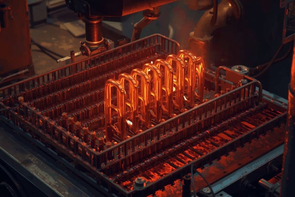
Replacing a heating element in an electric fireplace is most successful when it is treated as a controlled electrical service task rather than a “swap and hope” repair. The reliable sequence is: confirm the fireplace is de-energized, verify the fault with a multimeter (element continuity, thermal cutoffs, and connector condition), match the replacement part by required **voltage** and **wattage** plus physical fit, install with secure terminals and correct airflow clearances, restore all covers, then perform a short functional heat test. Heater engineering guidance describes a heating element as an assembly—conductive alloy plus insulating/support framework and lead connectors—so terminals and supports matter alongside the coil itself.
Related resources: Heating Element, Heating Element manufacturer, Heating Element Factory, Die Casting Heating Solutions.
- How electric fireplace heaters are built (and what usually fails)
- Symptoms and the fastest checks
- Safety boundaries for DIY work
- Diagnosis workflow (multimeter-first)
- Choosing the correct replacement element
- Replacement workflow (model-agnostic)
- Post-repair verification and performance checks
- Preventing repeat failures
- FAQ (7)
- References and outbound links
How electric fireplace heaters are built (and what usually fails)
Most electric fireplaces use a resistive heater paired with a fan to move warmed air into the room. The heater may be an open-coil or supported element, or a more enclosed/tubular style, depending on design and safety requirements. In engineering terms, a heating element is a component composed of both electrically conductive and insulating material, designed to serve a heating purpose. It is an assemblage that includes a framework (mica/ceramic supports in many designs) and lead connectors. Heat is produced by resistive (Joule) heating in the element alloy.
Most common failure points (ranked by field likelihood)
Electrical failure
Open heating element
Coil break or burn-out causes no heat; continuity test shows open circuit.
Connection failure
Loose terminals
High-resistance joints overheat, discolor, arc, and fail intermittently.
Protection event
Thermal cutoff
Overheat protection opens due to blocked airflow, dust, or fan issues.
Airflow failure
Fan / intake blockage
Reduced convection raises element temperature and shortens service life.
Section summary
Electric fireplace “no heat” problems frequently originate in the element, its terminals, or thermal protection devices triggered by poor airflow.
Symptoms and the fastest checks
A replacement decision should not start with parts shopping. It should start with symptom classification and quick checks that separate an element failure from a fan/control issue.
| Symptom | High-probability cause | Fastest check |
|---|---|---|
| Fan runs, no heat | Open element or open thermal cutoff | Continuity/resistance checks (power off) of heater and cutoffs |
| No fan, no heat | Power/control issue or fan motor problem | Confirm supply, inspect control settings, listen for motor activity |
| Heat cuts out after minutes | Overheat protection due to airflow restriction | Inspect intake/outlet, dust buildup, fan operation and noise |
| Burn smell / buzzing | Connector overheating or arcing | Inspect spade terminals for discoloration/melting; stop using until inspected |
What typically fixes “no heat” fastest (relative impact)
These impact levels represent practical prioritization, not universal statistics.
Section summary
The shortest route to a correct fix is to confirm fan airflow and then test the heater circuit electrically with the unit de-energized.
Safety boundaries for DIY work
Electric fireplace heaters operate on mains voltage and can draw substantial current. Safety best practice is consistent across appliances: verify correct replacement specifications, keep all wire connections tight, and restore protective covers before applying power.
When professional service is the correct next step
- Breaker trips, sparks, or repeated arcing
- Melted wiring insulation or burned terminal blocks
- Evidence of internal shorting to chassis
- Repair requires energized testing beyond basic verification
Section summary
Safe repairs begin with full de-energization and end with complete reassembly before power is restored.
Diagnosis workflow (multimeter-first)
Effective diagnosis combines visual inspection with electrical tests. This aligns with engineering guidance that heating elements are assemblies: a failure can occur at the coil, at the insulators/supports, or at the lead connectors.
Phase 1 — Visual inspection (high signal)
- Dust accumulation at intake/outlet and around the heater
- Terminal discoloration (blue/brown/black) indicating overheating
- Loose spade connectors (poor mechanical grip)
- Warped supports or element contact with metal housing
- Fan obstruction or abnormal fan noise
Phase 2 — Electrical checks (power off)
| Check | Expected result | What failure suggests |
|---|---|---|
| Element continuity/resistance | Continuity present; stable resistance | If open/OL: burned-out element |
| Thermal cutoff continuity | Continuity present | If open: overheat event or failed cutoff |
| Element-to-chassis short | No continuity to housing | If continuity: potential ground fault / contact short |
Interpretation principle
Manufacturer-style replacement guidance in other heater systems explicitly advises verifying the replacement element by referencing equipment voltage and wattage information, and ensuring wire connections are tight before energizing. Those two controls reduce wrong-part installs and connector overheating during fireplace heater service as well.
Section summary
Visual inspection identifies airflow and connector problems; continuity tests confirm whether the heater and thermal cutoffs are electrically intact.
Choosing the correct replacement element
Correct replacement is primarily a compatibility and specification task. A heating element must match the appliance’s electrical requirements and physical design. Consumer product listings for other heater types often show the fields that matter: wattage, materials, approvals, and warranty/returns.
Replacement specification checklist
| What to match | Why it matters | Risk if ignored |
|---|---|---|
| Voltage & wattage | Defines heat output and electrical load | Underheating, overheating, nuisance trips, unsafe operation |
| Form factor & mounting | Ensures correct clearance and airflow path | Element contact with housing, restricted airflow, noise/vibration |
| Terminal type | Secure mechanical/electrical connection | Arcing, connector heating, intermittent operation |
| Warranty/returns | Reduces downtime risk from wrong-part orders | Higher total cost of ownership |
How heater product families help specification discussions
Manufacturers commonly describe heater solutions by category—such as **heating tubes**, **heating plates**, **heating films**, and integrated die-cast modules— because each architecture has different heat-transfer and durability tradeoffs. For example, tubular heaters are described as using resistance wire with insulating material inside a sheath, while films emphasize thin, flexible heat distribution. Electric boiler heaters emphasize high-power liquid heating with flange connections and anti-scaling focus.
Section summary
Replacement success depends on matching electrical rating and physical integration, with attention to terminal quality and airflow clearance.
Replacement workflow (model-agnostic)
Exact disassembly differs by fireplace model. The workflow below focuses on the controls that reduce mistakes: documentation, connector integrity, and safe reassembly.
Workflow steps
- Isolate power at plug/breaker and confirm the unit is de-energized.
- Access heater compartment and remove dust buildup around intake and the heater housing.
- Photograph wiring at terminals and thermal cutoffs before disconnecting.
- Disconnect terminals by pulling on connector bodies, not wires; replace heat-damaged spades.
- Remove heater element and inspect supports/insulators and contact points.
- Install new element with correct clearance; ensure it cannot sag into the housing.
- Reconnect wiring firmly; confirm tightness and correct routing away from hot surfaces.
- Reinstall covers and ensure all protective shields are secured.
Section summary
The highest-value controls are wiring documentation, terminal replacement when heat-damaged, airflow cleaning, and restoring covers before power is applied.
Post-repair verification and performance checks
Post-repair verification should confirm both heat output and stable airflow without abnormal cycling. Overheating events often trace back to reduced airflow, so airflow is part of “pass/fail.”
Verification checklist
- All covers installed; no exposed wiring
- Fan starts and airflow is strong at outlet
- Heat output is present and stable
- No burning smell beyond brief dust-off (persistent odor indicates a problem)
- No abnormal noise/vibration from fan or heater mounts
| Post-repair result | Most likely cause | Next action |
|---|---|---|
| Fan runs, still no heat | Open cutoff, wiring mismatch, wrong part rating | Re-check continuity and wiring photos; verify voltage/wattage match |
| Heat starts then stops | Overheat cutoff due to airflow restriction | Stop use; clean intake/outlet; check fan operation |
| Breaker trips | Short to chassis or pinched wire | Stop use; inspect routing/insulators; professional service recommended |
Section summary
A successful repair produces stable heat with strong airflow and no electrical faults, after full reassembly.
Preventing repeat failures
Heater engineering references emphasize that environment and integration affect longevity, and that hidden costs appear when heaters fail repeatedly in the field. For electric fireplaces, the “environment” is typically dust and restricted airflow rather than water chemistry. A simple preventive routine reduces thermal stress and connector overheating.
| Preventive action | Why it works | Recommended cadence |
|---|---|---|
| Dust removal at intake/outlet | Improves convection; reduces element temperature and cutoff trips | Seasonally (or more in dusty environments) |
| Terminal inspection | Prevents connector resistance heating and arcing | During annual cleaning or whenever odor/noise appears |
| Fan performance check | Airflow is required to keep element within design limits | Before heating season |
Section summary
Most repeat failures are prevented by maintaining airflow and connector integrity, reducing thermal stress and shutdown events.
FAQ
1) Can an electric fireplace still show flames even if the heater is failed?
Yes. Many units separate the flame effect from the heating circuit, so the visual display can work while the heater does not.
2) What is the fastest way to confirm an element is burned out?
A power-off continuity/resistance test across the element terminals is the fastest confirmation of an open circuit.
3) Why do terminals and connectors matter as much as the element coil?
Engineering guidance defines the heating element as an assembly that includes lead connectors and an insulating framework. Loose terminals can generate localized resistive heating and arcing, causing intermittent heat or complete failure.
4) What causes the heater to shut off after a few minutes?
Overheat protection commonly opens when airflow is restricted by dust buildup or fan issues, raising element temperature.
5) What should be verified before installing a replacement heater?
Confirm correct physical fit, terminal type, and electrical rating. Manufacturer-style guidance for other heater replacements explicitly calls for verifying voltage and wattage against the equipment data plate.
6) Is it acceptable to bypass a thermal cutoff for testing?
No. Bypassing protection devices creates significant safety risk and can mask the underlying airflow problem that caused the cutoff to open.
7) What are “quality signals” when buying a replacement part online?
Clear specification fields (wattage, materials), safety approvals where applicable, and transparent warranty/returns policies reduce wrong-part and premature failure risk.
Conclusion
Electric fireplace heater replacement is best executed as a measured service workflow: confirm the fault with a multimeter, correct airflow constraints, match the replacement part by voltage/wattage and fit, install with tight terminals and proper clearance, then verify stable heat output after full reassembly. This approach aligns with heater engineering principles and reduces repeat failures that drive the true cost of “cheap” repairs.
References and outbound links
The sources below were used to ground definitions (heating element as an assembly, materials and frameworks), safety/verification principles (rating checks, tight wiring, secured covers), and procurement discipline (spec fields, warranty/returns).
-
Heating element engineering overview (assemblies, alloys, suspended/embedded/supported frameworks, environment, hidden costs):
https://tutco.com/conductive/heating-elements -
Example of safety and replacement verification discipline (verify voltage/wattage; tight wire connections; covers secured):
https://www.whirlpoolwaterheaters.com/support/help/element-was-out-of-range/24 -
Manufacturer product-family context and capabilities (heating elements, tubes/plates/films, integrated modules):
https://jinzho.com/
https://jinzho.com/product-category/heating-element/
https://jinzho.com/product-category/heating-element/heating-tubes/
https://jinzho.com/product-category/heating-element/heating-plate/
https://jinzho.com/product-category/heating-element/heating-film/
https://jinzho.com/product-category/die-casting-heating-solutions/
https://jinzho.com/product-category/electric-heater-parts/electric-boiler-heater/
https://jinzho.com/about/ -
Example of a consumer heater listing showing spec fields (1000W, materials, IP rating, UL approval, warranty/returns):
https://usa.hudsonreed.com/1000-plug-in-watt-electric-heating-element-76309
Disclaimer: This article is general educational content. Electric fireplace designs vary by manufacturer and model; always follow the unit’s service documentation and local electrical safety practices.