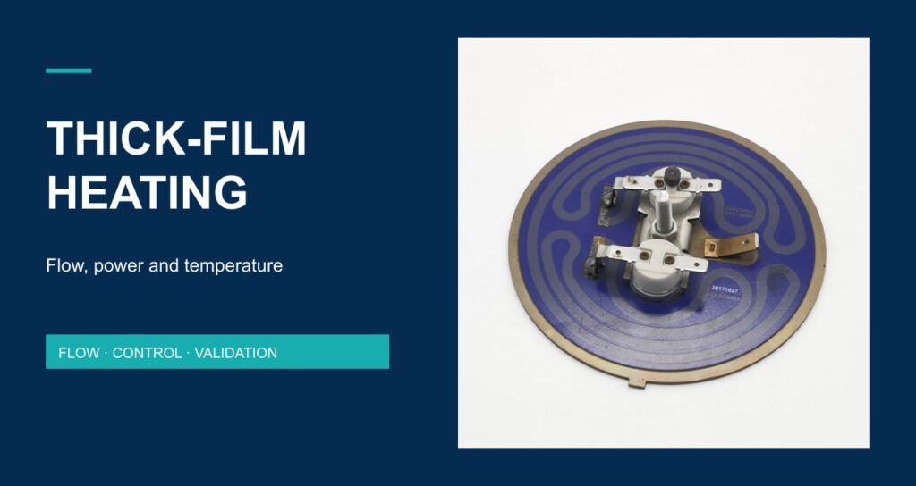
A thick-film water heater should be selected against an operating window: inlet temperature, water flow, required outlet temperature and the electrical power available under the actual control conditions. A compact heater can respond quickly, but the complete appliance still has to manage changing flow, sensor delay and interruptions in water supply.
For OEM coffee equipment and instant-water appliances, begin with the delivery requirement. Then check whether the chosen water path, printed heating assembly and control arrangement can meet it repeatedly. This guide uses a transparent single-phase water calculation to identify the questions worth resolving before prototype approval. It does not state the operating limits of any Jinzhong model.
1. Define the heating architecture and the measurement boundary
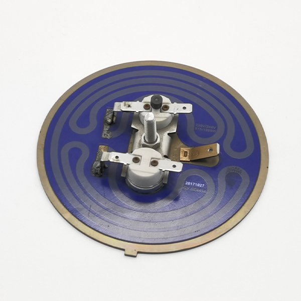
The term thick-film heater does not, by itself, describe the complete water-heating assembly. Confirm which surface carries the heating circuit, which surfaces contact water, how electrical insulation is provided and how the heater connects thermally to the fluid. A flat heating plate, a tubular component and an integrated water-path assembly require different installation details.
Jinzhong’s supplied company profile includes a thick-film heater presentation for a direct water dispenser. The current website also lists a thick-film heating element and a flat thick-film heater for coffee machines. These are starting points for a design discussion, not evidence that every format has the same water path, rating or control interface.
Specify useful heat at the appliance outlet
Write down where temperature is measured and what delivery interval matters. Water at a heater outlet, water after downstream tubing, and water arriving at a dispensing point can have different temperatures and delays. Measure and report the same boundary when comparing samples. A sensor attached to a heater surface does not directly establish the water temperature at a distant outlet.
| Requirement | Define before selecting a component | Why it matters |
|---|---|---|
| Water inlet | Temperature range and water condition | Required energy changes with inlet temperature |
| Delivery | Flow range, outlet target and draw duration | A nominal wattage cannot establish all three |
| Electrical supply | Actual voltage and permitted control method | Full-on input and time-averaged power differ |
| Installation | Water path, orientation, seals, mounting and sensor positions | The assembly determines heat transfer and measurement delay |
| Operating sequence | Start, draw, pause, refill and shutdown conditions | Transitions may differ from steady operation |
2. Use a flow-and-energy balance before quoting performance
The single-phase steady-state relationship
For a simple planning calculation, P = ṁ c ΔT. P is heat transferred to the liquid in watts, ṁ is mass flow in kg/s, c is specific heat in J/(kg·K), and ΔT is the water temperature rise in kelvin. The heat-capacity basis is described in the OpenStax heat-transfer reference. The flow form follows by applying the energy balance per unit time.
If flow is specified in litres per minute, convert it to mass flow before using the equation. For the illustrative calculation below, density is approximated as 1 kg/L and specific heat as 4,180 J/(kg·K). These constant-property assumptions are useful for screening requirements, but they are not a substitute for a model-specific thermal and hydraulic assessment.
Worked example: selected heat input of 1,500 W
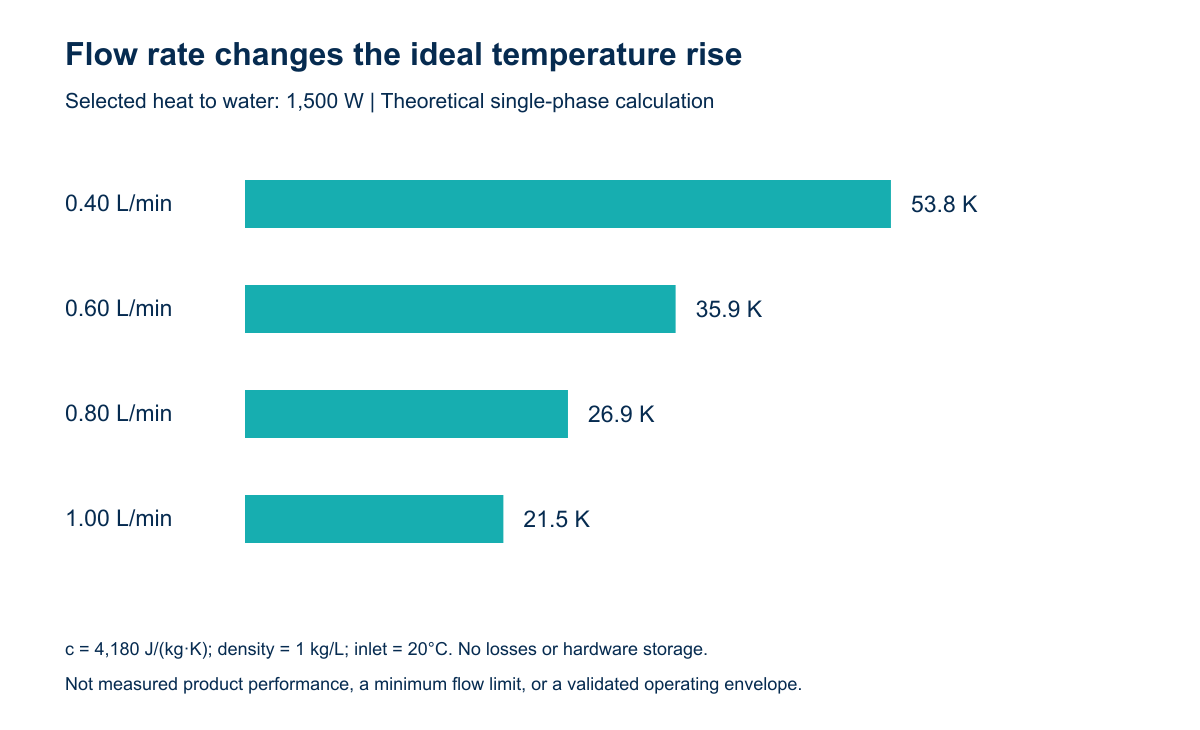
Assume 1,500 W reaches the water continuously, the inlet is 20°C, the water remains liquid, and there is no heat loss or energy stored in the hardware. This is a hypothetical ideal case, not a product rating. At 0.60 L/min, mass flow is 0.010 kg/s, so ΔT = 1,500 / (0.010 × 4,180) = approximately 35.9 K. The calculated outlet temperature is approximately 55.9°C.
| Selected flow (L/min) | Mass flow (kg/s) | Calculated rise (K) | Calculated outlet from 20°C |
|---|---|---|---|
| 0.40 | 0.00667 | 53.8 | 73.8°C |
| 0.60 | 0.01000 | 35.9 | 55.9°C |
| 0.80 | 0.01333 | 26.9 | 46.9°C |
| 1.00 | 0.01667 | 21.5 | 41.5°C |
Use the result to challenge an incomplete requirement
The example shows why “instant hot water” needs a flow and temperature definition. Increasing flow at fixed heat input reduces the temperature rise. Holding a higher outlet target at the same flow requires a larger energy rate unless another boundary condition changes. Before increasing the electrical rating, review whether the available supply, water path and protection architecture support the revised requirement.
For a controlled heater, useful average heat is not necessarily equal to nameplate input. Measure the actual electrical conditions and the delivered fluid result. Do not assume an efficiency percentage to make a calculation match a marketing claim. If the duty includes steam, use an enthalpy balance that includes phase change; the hot-water versus steam duty guide explains that distinction.
3. Specify low-flow and interrupted-flow behaviour separately
The flow equation becomes unsuitable as flow approaches zero. Dividing by a small flow does not prove that a real outlet can reach an arbitrarily high temperature. Heat may instead accumulate in the substrate and fittings, local conditions can change, and the operating assumptions may fail. The design therefore needs defined behaviour for reduced flow, interrupted flow and restart.
Temperature feedback and flow information answer different questions
An outlet temperature measurement describes a location at a particular time. A flow measurement or other validated water-presence signal describes another part of the operating state. Review what the controller knows before power is applied, while flow changes, and after flow stops. The correct sensing arrangement depends on the selected heater and appliance; there is no universal sensor layout in this guide.
A short water path or low thermal inertia does not eliminate sensor lag. Delay can arise from sensor response, water travel time, signal filtering and the control sequence. Check where peak temperatures occur during start, stop and restart rather than relying only on a stable reading during a long draw.
| Condition to investigate | Record in the prototype test | Engineering decision |
|---|---|---|
| Normal steady flow | Inlet/outlet temperatures, measured flow, supply and input power | Whether the stated delivery point is achieved |
| Changing flow | Flow transition, sensor traces, controller state and outlet response | Whether modulation and sensing handle the transition |
| Interrupted supply | Initial state, loss-of-flow indication and protective response | Whether power is removed by the intended architecture |
| Restart after a pause | Pause duration, retained water state and first delivered water | Whether overshoot and recovery meet agreed criteria |
| Representative service condition | Water condition and agreed cleaning/service history | Whether performance remains acceptable for the defined use |
4. Review construction, water chemistry and the control interface
Confirm the actual wetted materials, dielectric system, connection details and mounting requirements for the selected drawing. A stainless substrate description does not identify every wetted part or establish suitability for every water chemistry or cleaning agent. Likewise, a material grade named on a different catalogue item should not be copied into this assembly’s specification.
The stainless-steel thick-film heating tube listing illustrates a different form factor to review with its own drawing. Do not infer that its mounting, water path or electrical configuration can be exchanged with a flat module. Ask the supplier to identify the complete scope of supply, including seals, terminals, sensors and any attached protective devices.
Water-side deposits can change the heat-transfer conditions. Define the intended water quality and cleaning method, and agree how representative service conditions will be assessed. Do not invent a descaling interval or a universal water-hardness limit without evidence for the actual assembly and appliance.
Keep regulation and protective functions distinct
Normal outlet-temperature control and independent protection serve different purposes. Review the consequences of a failed sensor, a switching device that remains on, inadequate water supply and an interrupted control signal. Assign the required protective functions and their assessment at the complete-appliance level. A heater photo, rapid-response description or generic certification label cannot establish the safety of the finished integration.
5. Agree an operating-window acceptance record
A useful prototype report should make it possible to repeat the same test on the next sample. Identify the drawing revision, supply, control configuration, water conditions, sensor positions and operating sequence. State the endpoint and the allowed variation before collecting results. Keep calculated planning values separate from measured delivery and do not label a single demonstration as a complete endurance qualification.
| RFQ or acceptance field | Information to send Jinzhong |
|---|---|
| Application and duty | Appliance type; hot-water or steam duty; draw and pause sequence |
| Thermal requirement | Inlet range, required outlet condition and actual flow range |
| Electrical integration | Supply, control approach, connections and available protective architecture |
| Mechanical/hydraulic integration | Envelope, orientation, ports, water path, seals and mounting drawing |
| Evidence and documentation | Prototype quantity, test boundaries, acceptance criteria and target-market documentation |
Jinzhong’s company profile provides context for discussing heater formats and appliance integration. To begin a specific review, send the required water-flow range, temperature targets and interface drawing. This gives the supplier a clearer basis for selecting and validating a component than a request for a fast heater with the same outline.
Frequently asked engineering questions
Does thick-film construction guarantee a particular outlet temperature?
No. Outlet temperature depends on heat input, flow, inlet condition, heat transfer and control behaviour. Define these conditions and verify the complete appliance. Construction type alone does not establish the delivery result.
Can the theoretical flow calculation define a minimum safe flow?
No. It is a single-phase energy balance under stated assumptions. A minimum operating flow requires assessment and validation for the actual heater, water path, sensing and protective functions.
Can a flat heater and a tubular heater use the same acceptance test?
They can be compared against the same appliance delivery requirement, but each needs its own installation and operating configuration identified. Equal wattage or similar appearance does not establish interchangeability.
Which evidence should accompany a fast-response claim?
Ask for the initial condition, measured flow, inlet temperature, supply, control state, sensor location and endpoint. A surface-temperature response and a useful outlet-water response are different measurements.
Sources and calculation basis
Company context was checked against the supplied Jinzhong Company Profile.pdf thick-film presentation, the supplied product workbook and the linked current product pages. The original photograph is supplied file 3001/1.jpg and is used only to illustrate visible construction. Table 2 and Figure 1 use the stated ideal inputs; they are not product test data. No model-specific power range, efficiency advantage, minimum flow, lifespan or certification is asserted.