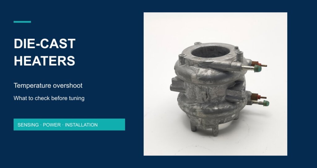
A die-cast heater reaches the controller setpoint, power is reduced, and the measured temperature continues to rise. Before changing PID gains, establish which temperature is overshooting and whether electrical power has actually fallen. The controller display, casting surface and useful process output describe different locations in a thermal system.
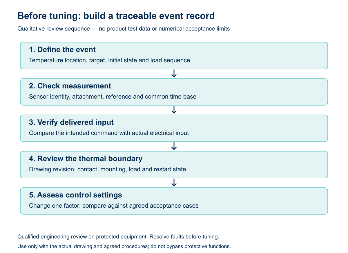
For an OEM investigating die-cast heater temperature overshoot, a useful first result is a repeatable event record that separates measurement, power delivery and thermal response. This guide provides that record and a decision sequence. It does not prescribe controller gains, a permitted overshoot or a test involving defeated protection.
1. Define the temperature that must meet the requirement
Write the acceptance requirement around the useful output: a contacted part, a liquid outlet or another defined process location. Then identify the sensor used for regulation. A casting-mounted sensor may be useful for control, but its reading alone does not establish the temperature at a remote outlet or load. Record both locations where the engineering question requires both.
Specify the initial condition and operating sequence as well. A cold start, restart after a pause and change in load need separate labels. Comparing a cold-start trace against a warm restart can look like a control inconsistency even when the two runs began with different stored energy.
| Record | Definition to agree | Why it matters |
|---|---|---|
| Controlled temperature | Sensor type, position, attachment and filtering | Identifies what feedback reaches the controller |
| Acceptance temperature | Process location, measurement method and target | Identifies the result required by the equipment |
| Overshoot metric | Peak above the stated target during a defined event | Avoids comparing different endpoints |
| Initial and load state | Start temperatures, prior operation and load sequence | Makes runs comparable |
2. Use the product photograph to prepare a drawing review
The supplied assembly photograph below shows a central opening, a cast exterior and electrical terminal ends. It does not reveal the internal heating distribution, a water path, a sensor location or a calibrated measuring point. These need the correct drawing. A visible recess is not evidence that a sensor can be installed there.
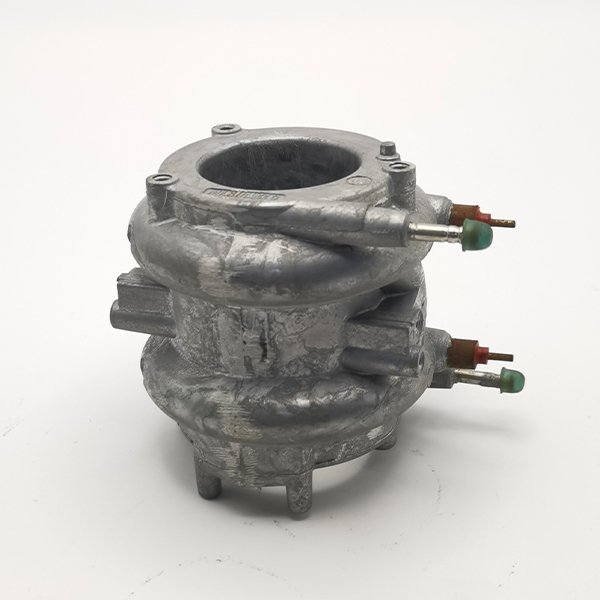
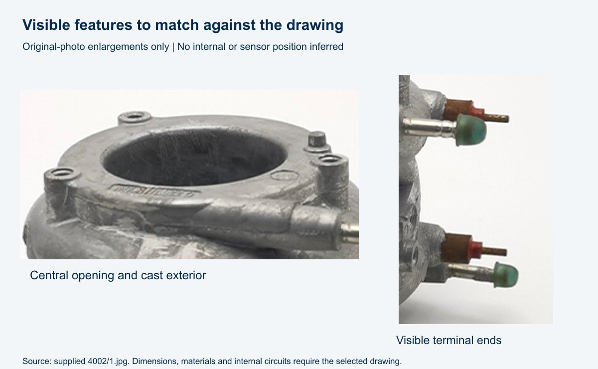
Ask for a drawing that identifies active heating zones, the intended load interface, the proposed regulation sensor and protective devices. Compare the sensor attachment and assembly revision on the sample with that drawing. If they differ, resolve that discrepancy before treating tuning as the main cause.
3. Separate the command from delivered power
A controller output command is not a direct measurement of heater input. Review how the output device is intended to switch or modulate power, then have a qualified person verify the delivered input using an appropriate method. Keep the command, measured input and temperature records on a common time base.
If power remains present when the intended command is off, investigate the electrical and control path before thermal tuning. A continued temperature rise after input has fallen may instead reflect thermal redistribution, changing heat removal or measurement delay. Neither observation, by itself, proves the casting is defective.
| Observation | Check next | Do not infer yet |
|---|---|---|
| Displayed temperature differs from reference | Sensor identification, attachment, reference location and signal processing | That all difference is a controller-gain problem |
| Delivered power does not follow intended command | Switching configuration, wiring and output-device behaviour | That temperature tuning will correct the fault |
| Power falls but process temperature continues rising | Temperature distribution, retained heat, sensor response and load change | That a particular overshoot magnitude is normal |
| Only restart or low-load operation is affected | Prior thermal state, pause duration and load sequence | That cold-start acceptance covers the same condition |
4. Check sensor response and the heat-transfer path together
The feedback location affects what a controller can detect and when it detects it. A sensor remote from the relevant heat-transfer path can respond late; moving it also changes what temperature is represented. Review location and attachment together with the operating load rather than assuming that any position on a metal body is equivalent.
For general background, Watlow’s sensor-placement guidance discusses the relationship between heat source, sensor and load. It is a general control principle, not a Jinzhong installation drawing. It does not establish a mounting position for the photographed component.
Distinguish an installation change from a control change
Contact, orientation, fastening and load conditions are part of the thermal system. Compare the intended installation with the test fixture. If the sample is intended to transfer heat into another part, a bench arrangement with different contact can produce a different response. Do not assign a generic torque, contact compound or flatness value without the relevant specification.
Change one factor at a time and identify the revision in the record. Changing sensor attachment, load and controller settings together can produce a better-looking trace without showing which change mattered. Retain unsuccessful runs as well as the preferred result so the comparison remains reviewable.
5. Build a repeatable record before deciding on tuning
Once measurement, power delivery and installation are understood, assess control settings against the stated use cases. Keep normal regulation and independent protective functions distinct. Their required behaviour must be reviewed for the complete appliance; a stable controller display does not demonstrate protection against every fault.
| Run family | Keep identified | Compare against |
|---|---|---|
| Cold start | Initial temperatures, supply, load, sensor arrangement and settings | Agreed peak and useful-output criteria |
| Restart after a pause | Prior duty, pause duration and retained thermal state | Separate restart criteria |
| Defined load transition | Load before/after, transition time and input response | Agreed transient and recovery criteria |
| Repeat run | Same configuration, instruments and event definition | Repeatability requirement agreed by the team |
A supplier review is more useful when it contains the drawing revision, marked sensor locations, electrical connection, actual input measurement, initial state and event timeline. Add photographs of the fixture and mounting. Include the acceptance definition and explain whether the issue concerns the casting sensor, process output or both.
What to send Jinzhong for an assembly review
The supplied company profile identifies die-cast heaters and accessories as a Jinzhong product family. The die-casting heating solutions catalogue and die-casting heater listing are starting points for a component discussion; confirm the selected drawing and scope of supply. No integrated sensor, controller, response time or certification is assumed for every listed assembly.
For initial specification fields, see the die-cast heater OEM selection checklist. This article addresses a later question: how to organize evidence when a temperature transient does not meet the requirement. Send the assembly drawing and overshoot event record to Jinzhong for a configuration-specific review.
Frequently asked questions
Does temperature rising after switch-off prove an electrical fault?
No. First verify the actual delivered input. When input has fallen, temperatures at different locations may still change as stored heat redistributes. A single trace cannot distinguish all causes.
Should the sensor always be moved closer to the heater?
No universal relocation is justified here. The location must represent the control objective and work with the load, protection architecture and approved mounting design. Repositioning requires validation.
Can the same controller settings be accepted for every assembly?
Do not assume that. A different geometry, mounting, load or sensing arrangement changes the system being controlled. Assess the actual configuration against the agreed events and acceptance criteria.
Sources and limits
Company evidence: supplied Jinzhong Company Profile.pdf, pages 15 and 19, and Jinzhong Company and Product Introduction.pdf, page 30. Original image: supplied product folder 4002/1.jpg. The workflow and tables are qualitative engineering review tools; they are not a customer case, measured product test or certification protocol. Unverified marketing temperature, response-time, efficiency, compatibility and lifetime claims are excluded.