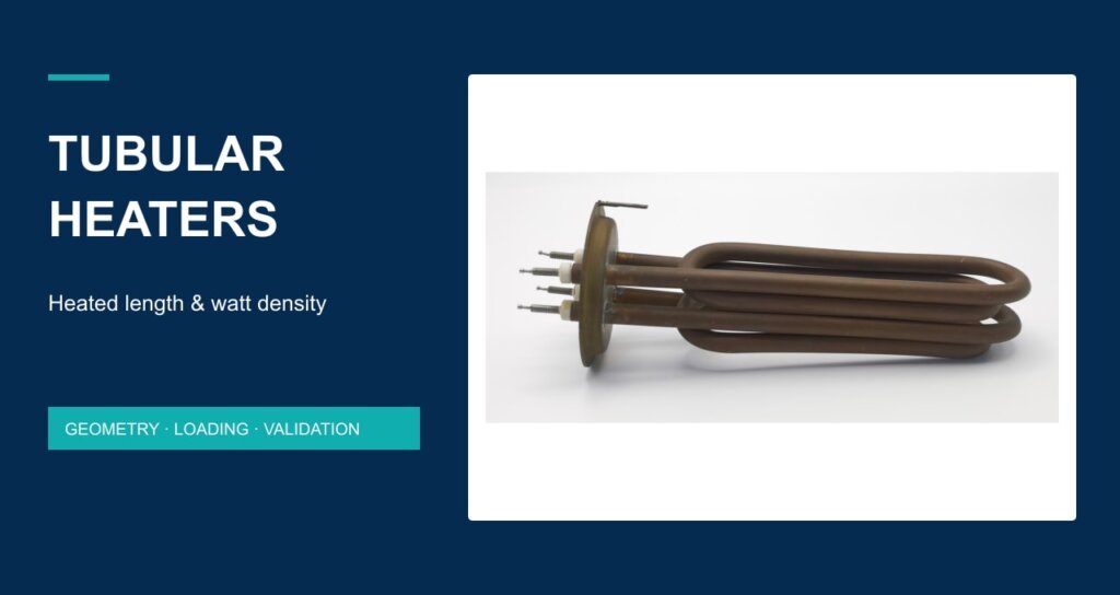
Two tubular heaters can have the same electrical rating and impose very different loads on their sheaths. For OEM selection, total watts answer only part of the question. The active heated length, tube diameter and installation conditions determine how that power is distributed and how it can leave the element.
Start with the process heat requirement, then calculate the nominal surface loading and review the actual heat-transfer boundary. This guide explains that workflow for round tubular elements. It does not provide a universal safe watt-density limit or substitute for a supplier-approved drawing and prototype assessment.
1. Separate the heat requirement from the element layout
State what the equipment must heat, from which initial condition, over what operating sequence. A process that heats a batch, holds a tank at temperature or warms flowing air presents different conditions even when the calculated power is similar. Include startup, steady operation and foreseeable changes in heat removal in the requirement.
Next identify how many elements share that duty, how they are connected and which sections generate heat. The overall insertion dimension is a mechanical envelope; it is not automatically the active heated length. Terminal sections, cold zones and mounting allowances must be identified on the selected drawing before calculating surface loading.
| Requirement | Record in the RFQ | Reason |
|---|---|---|
| Process duty | Medium, initial/target conditions, startup and hold sequence | Defines required heat input and operating cases |
| Electrical arrangement | Supply, connection, power per element and control sequence | Prevents using bank power as single-element power |
| Heated geometry | Outside diameter and developed active length per circuit | Defines the nominal heated sheath area |
| Installation boundary | Immersion, air, radiation or contact; orientation and obstructions | Determines how heat can leave the sheath |
2. Calculate nominal watt density from active surface area
For a round tube with uniform outside diameter, the lateral surface area of the active section is A = π × D × Lh. Nominal watt density is q = P / A. Use D and Lh in centimetres to obtain A in cm², then P in watts gives q in W/cm². Developed length follows the tube centreline through bends; it is not the straight-line distance from flange to tip.
For a bank, calculate each element or powered section against its own active area. Dividing total bank power by one tube’s area overstates loading; counting inactive length understates it. If the construction has deliberately unequal heat distribution, a single average cannot describe its local loading. Request the heating-zone layout.
Worked example: the same power with different active lengths
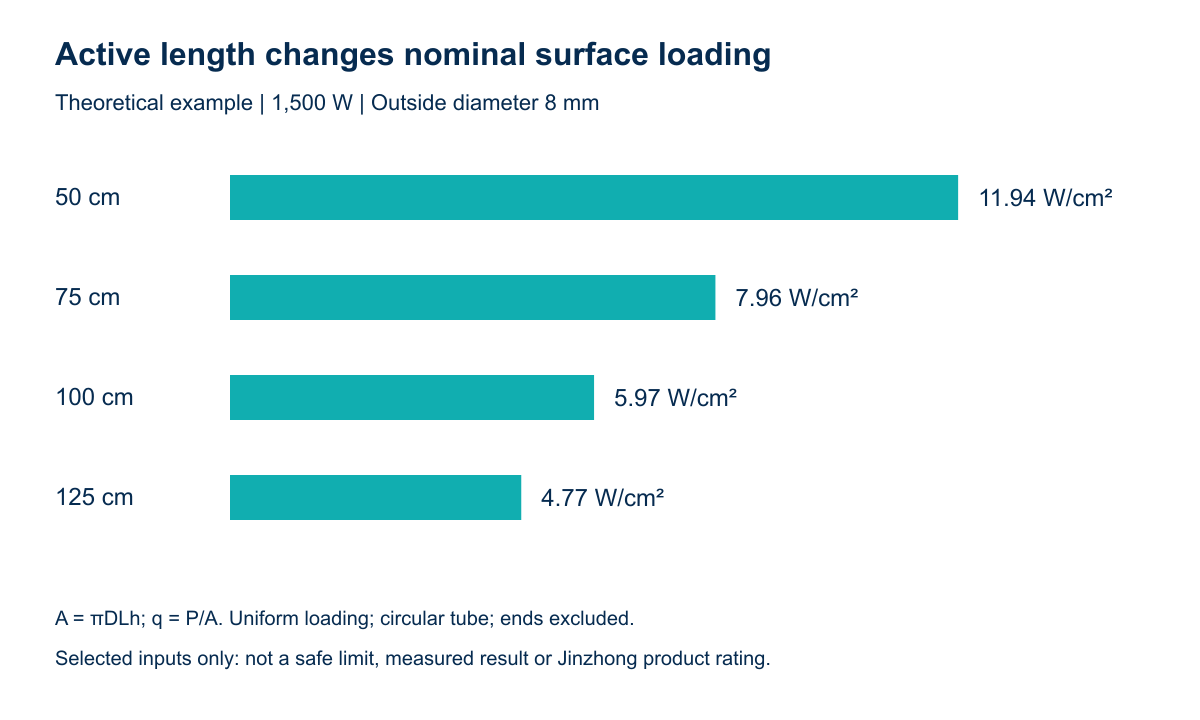
Select a hypothetical round element with P = 1,500 W and D = 8 mm = 0.8 cm. Compare active developed lengths of 50, 75, 100 and 125 cm. These are calculation inputs selected to show geometry; they are not Jinzhong product dimensions, approved operating points or measured performance.
| Active length Lh (cm) | Lateral area A (cm²) | Nominal q (W/cm²) |
|---|---|---|
| 50 | 125.7 | 11.94 |
| 75 | 188.5 | 7.96 |
| 100 | 251.3 | 5.97 |
| 125 | 314.2 | 4.77 |
How a length-definition error changes the result
At an assumed active length of 100 cm, the example gives about 5.97 W/cm². If the same drawing actually contains only 80 cm of active length, the value becomes about 7.46 W/cm². That is 25% higher because the active area is smaller. The arithmetic is useful for finding a specification error; it does not show whether either configuration is acceptable in the application.
3. Match surface loading to the heat-transfer boundary
Watt density is a screening parameter, not a temperature setting. Two equal-density elements can operate at different sheath temperatures when their surroundings remove heat differently. The selected sheath, medium, flow, mounting and control arrangement therefore need to be reviewed together. Manufacturer application guidance also treats watt density as application-dependent; see the Watlow application guide for the general active-area method. Its product ratings must not be transferred to a Jinzhong component.
| Boundary | Information to check | Condition to assess |
|---|---|---|
| Liquid immersion | Minimum level, orientation, circulation, deposits and actual chemistry | Exposure of an active section or reduced local heat removal |
| Air heating | Air path, measured flow distribution, inlet condition and spacing | Blocked or uneven airflow near individual tubes |
| Contact heating | Contact geometry, restraint, fit and thermal expansion | Loss of contact or a gap around part of the active length |
| Radiant/enclosed heating | Element spacing, surrounding surfaces and operating cycle | Changes in the surrounding thermal environment |
An average value also conceals local conditions. Part of an element may be shaded from airflow, exposed above a liquid level or installed against a different contact surface. Do not treat the presence of a temperature sensor elsewhere in the equipment as evidence that every active section is adequately cooled.
Cold zones and mounting details belong on the same drawing
Show the transition from active length to terminal or mounting regions. Identify fittings, seals, clearances and the intended installation orientation. When a bend or fitting changes, ask whether the active-length definition or heating distribution also changes. A replacement that fits the opening may still impose a different local thermal condition.
4. Review the Jinzhong product against a specific duty
The supplied Jinzhong Company Profile identifies a heating-tube product family and an industrial heating-tube presentation. The Industrial heating tube product page is a starting point for discussing the required format. The heating-tube catalogue provides other forms to review when the envelope or mounting differs. Confirm the selected construction and dimensions with the supplier instead of combining specifications from different listings.
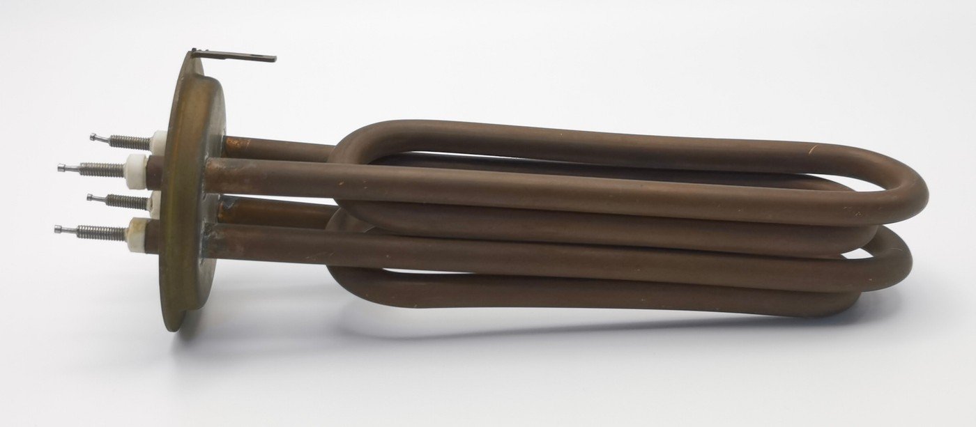
A material name alone does not establish suitability for every process. Define the actual medium, chemistry, operating cycle and expected cleaning conditions, then ask for the specified sheath and joint construction. Likewise, a general catalogue temperature range is not a validated continuous sheath limit for a particular assembly.
5. Agree prototype evidence before releasing the design
Keep calculated planning values and measured acceptance results separate. A useful prototype record identifies the drawing revision, sample, electrical configuration, installation, process condition, sensor locations and test sequence. Measure the conditions actually present rather than relying only on controller settings.
| Review item | Evidence to request | Acceptance decision |
|---|---|---|
| Drawing and active zones | Marked developed length, diameter, cold zones and tolerances | Calculation uses the actual geometry |
| Electrical input | Supply and input per element in the intended connection | Power basis matches the selected duty |
| Thermal operation | Process and relevant sheath temperatures with sensor locations | Defined operating cases meet agreed limits |
| Control and protection | Control sequence and assessment of loss of heat removal | Protective response is assessed at equipment level |
| Service conditions | Representative deposits, cleaning and cycling plan where relevant | Service assumptions are addressed without invented lifespan claims |
Normal regulation and protective functions need separate consideration. A process controller that holds one sensor at a target does not, by itself, demonstrate adequate protection after sensor failure, switching failure or loss of the intended heat-removal condition. Review these cases in the equipment design before conducting tests.
For an application review, send Jinzhong the duty, active-length drawing and installation conditions. Include the medium, supply, number of elements, operating cycle and acceptance requirements. This gives the supplier a concrete basis for reviewing surface loading and the scope of supply.
Frequently asked questions
Does a lower watt density guarantee longer life?
No. The calculation describes nominal electrical loading per active surface area. Service outcome also depends on construction, operating conditions, contamination, cycling and installation. The examples above do not predict lifetime.
Can overall tube length be used instead of heated length?
Only if the drawing confirms that the entire counted length is active for the power being evaluated. Otherwise use the active developed length and exclude cold sections. Keep the power and area boundaries consistent.
Can an immersion rating be reused in air?
Do not assume interchangeability. Air and liquid installations create different heat-transfer boundaries, and the element needs assessment for its actual medium, mounting, control and operating conditions.
Sources and calculation basis
Company context: supplied Jinzhong Company Profile.pdf, pages 16 and 41, and the linked current catalogue. Product image: supplied folder 1002 original photograph. Table 2 and Figure 1 are reproducible calculations using explicitly selected inputs, not laboratory results. No product-specific safe watt density, efficiency, temperature range, lifespan or certification is claimed.