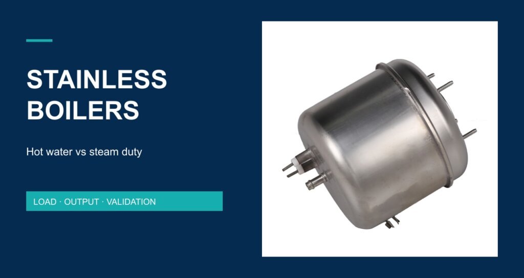
A caldaia in acciaio inossidabile deve essere dimensionata in base al calore erogato al suo fluido di lavoro, piuttosto che alla sola potenza nominale di targa. Riscaldare acqua e produrre vapore sono compiti diversi. La specifica utile definisce le condizioni di ingresso, le condizioni di uscita, la domanda nel tempo e l'assieme completo che deve soddisfarle.
Per un apparecchio OEM, la domanda chiave non è semplicemente “Quanti watt?” Ma “Cosa deve uscire dalla caldaia, in quale condizione e per quanto tempo?” Questa guida separa tali questioni utilizzando un bilancio energetico trasparente, quindi collega il calcolo alla costruzione del recipiente, alle interfacce e all'accettazione del prototipo. Gli esempi numerici sono calcoli ipotetici, non valori nominali o risultati di prova dei prodotti Jinzhong.
1. Definire il requisito di erogazione prima di selezionare una caldaia
Una caldaia può far parte di una macchina per caffè, di un apparecchio per la pulizia a vapore o di un ferro da stiro a vapore, eppure queste applicazioni non impongono la stessa domanda. Un breve impulso da energia immagazzinata è diverso da un'erogazione continua. Un sistema può soddisfare una breve dimostrazione e comunque fallire un ciclo operativo ripetuto perché non riesce a recuperare tra un prelievo e l'altro.
| Servizio | Specificare al confine dell'apparecchio | Cosa verificare |
|---|---|---|
| Acqua calda a lotti | Massa d'acqua; temperature di ingresso e target; stato di avvio a freddo | Tempo fino al punto finale concordato di temperatura dell'acqua |
| Acqua calda in flusso | Portata massica e temperature di ingresso/uscita | Stabilità della temperatura durante tutto il prelievo |
| Erogazione di vapore | Condizione dell'acqua di alimentazione; pressione di uscita; portata massica richiesta e condizione del vapore | Massa e condizione erogate in un intervallo definito |
| Impulsi di vapore intermittenti | Durata dell'impulso; intervallo; numero di impulsi; stato di riempimento iniziale | Recupero, comportamento in pressione e ripetibilità |
Separare l'energia immagazzinata dall'output sostenuto
Indicare se il test inizia a freddo, a prontezza normale o immediatamente dopo un ciclo precedente. Registrare la quantità di riempimento iniziale e lo stato del controllo del livello dell'acqua. Se un progetto utilizza acqua calda immagazzinata, il suo primo impulso può superare la portata sostenuta supportata dall'input elettrico. Riportare entrambi i risultati con le rispettive condizioni operative invece di combinarli in un'unica dichiarazione di output.
2. Perché un calcolo dell'acqua calda non può stabilire la capacità di vapore
Il riscaldamento dell'acqua liquida utilizza un bilancio di calore sensibile
Per un calcolo di pianificazione con acqua liquida e senza cambiamento di fase, Q = m c ΔT. Qui Q è l'energia, m è la massa d'acqua, c è il calore specifico e ΔT è l'aumento di temperatura. La relazione è descritta nel riferimento sul calore specifico di OpenStax. Utilizzare unità coerenti e dichiarare qualsiasi approssimazione a proprietà costanti.
Esempio svolto: un chilogrammo d'acqua
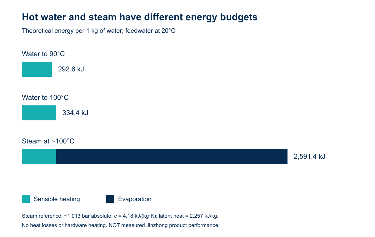
Supponiamo che l'acqua parta da 20°C. Usando c = 4,18 kJ/(kg·K), riscaldare 1 kg a 90°C richiede 292,6 kJ. Riscaldarlo a 100°C richiede 334,4 kJ con la stessa approssimazione. Nessuno dei due valori include l'evaporazione, il recipiente, i raccordi o il calore disperso nell'ambiente.
La generazione di vapore richiede anche calore latente
Per un caso atmosferico illustrativo, si assuma la temperatura di saturazione pari a circa 100°C a 1,013 bar assoluti e il calore latente di vaporizzazione pari a circa 2.257 kJ/kg. Questi sono valori di riferimento arrotondati, non una pressione operativa o un limite di accettazione per una caldaia fornita. La spiegazione della formazione del vapore di Spirax Sarco distingue il riscaldamento sensibile dall'energia aggiunta durante il cambiamento di fase.
Partendo da 1 kg di acqua liquida a 20°C, un bilancio energetico approssimativo per produrre vapore saturo secco a questa condizione atmosferica è 334,4 + 2.257 = 2.591,4 kJ/kg. Questo è circa 8,9 volte l'energia dell'acqua calda da 20 a 90°C in questo esempio. Non è un rapporto universale: la temperatura dell'acqua di alimentazione, la pressione e la condizione di uscita cambiano il calcolo.
| Attività illustrativa, per 1 kg | Energia sensibile (kJ) | Energia di evaporazione (kJ) | Totale (kJ) |
|---|---|---|---|
| Acqua: 20 → 90°C | 292.6 | 0 | 292.6 |
| Acqua: 20 → 100°C | 334.4 | 0 | 334.4 |
| Vapore: alimentazione a 20°C → vapore saturo secco a ~100°C | 334.4 | 2,257 | 2,591.4 |
Confine dell'esempio
This atmospheric example does not prescribe venting, a pressure setting or a test procedure for a real vessel. For a pressurised project, calculate the enthalpy rise from the actual feed condition to the specified outlet pressure and steam condition using suitable steam-property data. Distinguish absolute pressure from gauge pressure. The appliance and vessel design must be reviewed for the actual market and operating conditions.
3. Convert the energy budget into a power question
At steady state, the approximate ideal steam rate is ṁ = P / Δh, where P is heat transferred to the fluid in kJ/s and Δh is the required enthalpy rise in kJ/kg. Multiplying by 3,600 gives kg/h. Electrical input is not automatically identical to useful heat delivered to the fluid at the appliance outlet.
Using only the atmospheric example above, 1.5 kW corresponds to 1.5 × 3,600 / 2,591.4 = approximately 2.08 kg/h. This is an ideal, loss-free energy ceiling under the stated assumptions, not a proposed specification. Do not attach it to the pictured assembly or quote it as a production guarantee.
| Hypothetical continuous heat to fluid | Ideal steam rate, stated atmospheric case | What the number excludes |
|---|---|---|
| 1,5 kW | 2.08 kg/h | Startup, thermal losses, downstream losses and other loads |
| 2.0 kW | 2.78 kg/h | Same exclusions |
| 3.0 kW | 4.17 kg/h | Same exclusions |
Use prototype measurements to close the budget
Measure supply conditions, input power, initial water and metal temperatures, delivered output and the selected endpoint. Keep the test boundary consistent. A vessel sensor reaching its setpoint does not demonstrate that the outlet delivers the requested fluid condition. Condensate collection by itself also does not establish steam dryness when liquid carryover may contribute to the measured mass.
For intermittent service, define the whole duty cycle. Specify each burst, pause, refill event and recovery criterion. Compare results at the same initial state and repeat the sequence. A useful engineering report distinguishes cold-start readiness, first-burst behaviour and sustained repeat operation.
4. Review the stainless vessel and heater as one assembly
“Stainless steel” identifies a material family, not the complete wetted construction. Request the grade and finish of the actual water-contact parts, joining materials, seals and fittings. Evaluate them against water chemistry, cleaning agents, temperature cycling and the intended maintenance procedure. Do not infer the grade of a boiler from a grade listed for a different heating tube or tank product.
Welds, ports and mounting details affect the integration
Jinzhong’s supplied company profile identifies stainless steel boilers and describes stamping/deep drawing and TIG welding for this product presentation. It also identifies coffee machines, steam mops and handheld garment steamers as application examples. Those statements support an engineering discussion; they do not establish that every catalogue model uses identical construction or carries the same operating limits.
La stainless steel boiler heater listing e coffee boiler listing are starting points for identifying the required assembly. Confirm the selected drawing revision and construction before transferring any catalogue statement to an appliance specification.
| Interface or condition | Information to agree | Evidenza da richiedere |
|---|---|---|
| Vessel and joints | Materials, geometry, joining process, wetted surfaces | Drawing, material documentation and agreed inspection records |
| Ports and mounting | Thread/seal details, orientation, loads and clearances | Interface drawing and assembly instructions |
| Heater and control | Electrical configuration, sensor location, operating endpoint | Wiring information and prototype records |
| Leak/pressure verification | Method, medium, conditions, acceptance limits and traceability | Model-specific agreed procedure and recorded results |
| Manutenzione | Water quality, cleaning method, access and service interval basis | Validated instructions for the intended appliance |
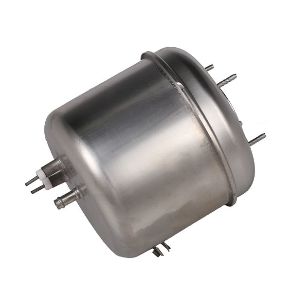
Where a project needs a separate vessel-bottom heating arrangement, review the boiler bottom with heating tubes with its own interface requirements. A bottom assembly is not automatically interchangeable with a complete boiler. Confirm which party supplies the vessel, heater, seals, sensors and protective functions.
5. Agree the acceptance record before ordering prototypes
Define useful delivery in terms the development team can reproduce. Record the supply, fluid condition, initial state, control settings and measurement locations with each test. A temperature curve without those conditions is difficult to compare with a later sample. Include the drawing revision and any firmware or control configuration that changes the result.
Normal temperature regulation and independent protective functions serve different purposes. Review low-water operation, interrupted supply, sensor faults and abnormal operating cases at the complete-appliance level. Determine the required protective architecture and applicable assessment with the responsible engineering team. A catalogue photograph or a pressure-test statement cannot replace that work.
Jinzhong’s company profile mentions pressure testing for its stainless boiler presentation, but does not provide a model-specific pressure, hold time or acceptance record for the assembly pictured here. Ask for those details for the selected model instead of converting a general process statement into a pressure rating. Background company information is available in the profilo aziendale di Jinzhong.
6. What to include in a stainless boiler enquiry
Send the intended appliance and output duty; feedwater conditions; required delivery temperature or steam condition; pressure basis; electrical supply; duty cycle; envelope and mounting; ports; sensing/control responsibilities; cleaning conditions; and documentation needed for the target market. Identify whether the request covers a complete boiler or only a vessel/heater subassembly.
For an engineering review, send Jinzhong the boiler duty cycle and interface drawing. The aim is a shared, testable requirement rather than a wattage-only enquiry. If the project is still choosing between a cast heating assembly and a separate boiler, the die-cast heating element design checklist covers the earlier assembly-definition stage.
Domande ingegneristiche frequenti
Can a hot-water flow result be converted directly into a steam output?
No. Steam production includes phase-change energy and a defined pressure and outlet condition. Use an enthalpy budget for the actual feed and outlet conditions, then verify the complete system. A liquid-water result alone does not establish steam capacity.
Does a higher power rating guarantee better steam performance?
Higher input can increase the available energy, but delivered performance depends on the heat-transfer path, control behaviour, water supply and losses. First-burst output and continuous output are separate results. Match the power and assembly design to the stated duty cycle.
Does stainless steel construction establish a pressure rating?
No. Material, thickness, geometry, joints, ports and operating conditions all matter. Use the selected assembly’s agreed technical documents and applicable assessment. A generic material description is not a vessel rating or a certification.
What should the supplier report with a prototype result?
At minimum, identify the tested configuration, initial state, supply conditions, fluid conditions, measurement locations, duty cycle and acceptance endpoint. Record actual output and the limits of the test. Distinguish calculated planning values from measured results.
Sources and calculation basis
Company statements were checked against the supplied Jinzhong Company Profile.pdf, pages 15 and 18, and the product/application workbook records. The original photograph is supplied file 7001/1.jpg. General heat and phase-change relationships are referenced above. Tables 2 and 3 and Figure 1 use explicitly selected theoretical inputs; no model-specific output, efficiency, endurance or certification claim is made.